Dyna-Force® Clamps
Measurements Available: Metric
Dyna-Force® Clamps
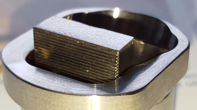
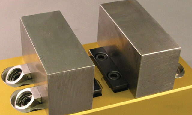
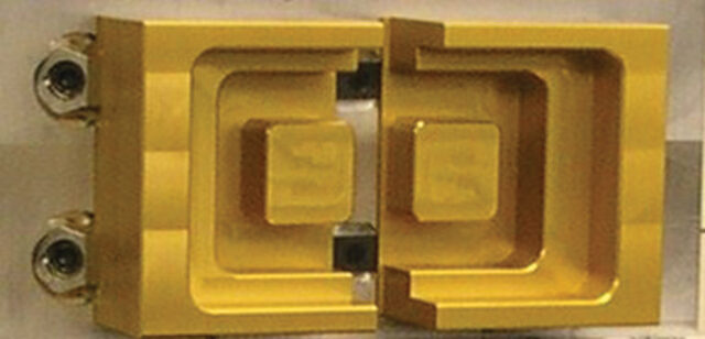
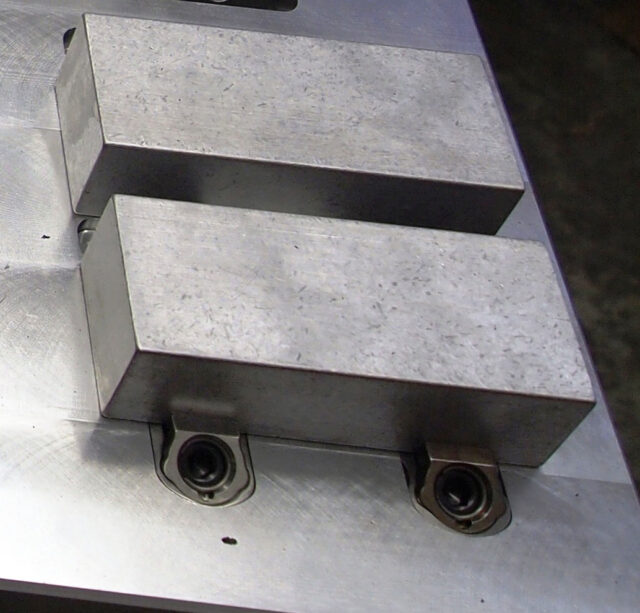
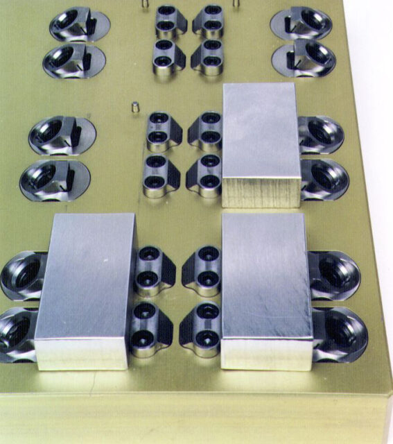
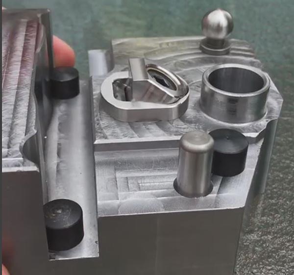
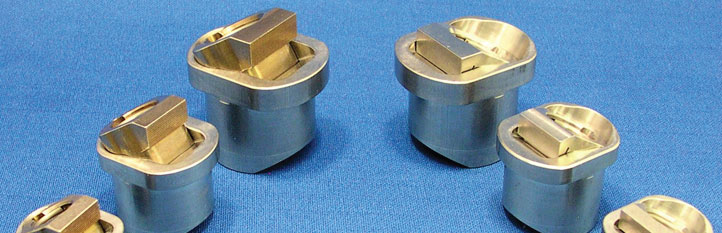
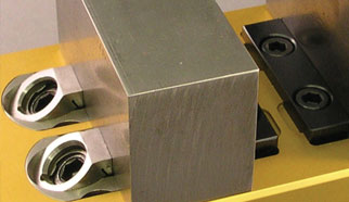
The majority of the Dyna-Force® clamp is below the surface of the fixture which provides excellent clamp support and makes for a very low profile. The clamp jaw slides on an angle for positive downforce.
The clamp jaw is available with smooth or serrated faces.
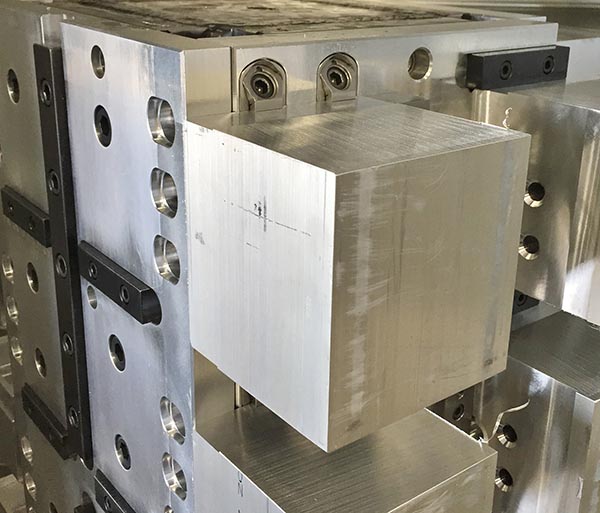
The support surface of the Dyna-Force® clamp can be installed flush with the fixure plate or raised to hold the workpiece off the fixture, enabling drill-through.
PATENT NO. 5964458 |
 |
Metric
| Part No. |
Clamp Jaw† & Hardness |
A* | B | C | D | E | F | — Min |
G Opt. |
— Max |
Clamp Travel |
Drive Screw |
Key Size |
Max Torque |
Holding Force |
Repl. Clamp Jaw Insert** |
|
|---|---|---|---|---|---|---|---|---|---|---|---|---|---|---|---|---|---|
| 28314 | CAD | Smooth 34RC | 20.00 | 24.90 | 19.00 | 19.90 | 4.50 | 13.50 | 3.25 | 5.00 | 6.75 | 2.0 | M6x12mm | 5mm | 7.3 (Ft/Lbs) 9.9 (N.m) |
2,000 (Lbs) 8896 (N.) |
28480 (smooth) |
| 28318 | CAD | Serrated 44RC | 20.00 | 24.90 | 19.00 | 19.90 | 4.50 | 13.50 | 3.25 | 5.00 | 6.75 | 2.0 | M6x12mm | 5mm | 7.3 (Ft/Lbs) 9.9 (N.m) |
2,000 (Lbs) 8896 (N.) |
28482 (serrated) |
| 28320 | CAD | Smooth 34RC | 25.00 | 29.90 | 24.00 | 24.90 | 5.00 | 15.00 | 4.50 | 6.50 | 8.25 | 2.2 | M8x16mm | 6mm | 17.6 (Ft/Lbs) 23.9 (N.m) |
2,600 (Lbs) 11565 (N.) |
28484 (smooth) |
| 28322 | CAD | Serrated 44RC | 25.00 | 29.90 | 24.00 | 24.90 | 5.00 | 15.00 | 4.50 | 6.50 | 8.25 | 2.2 | M8x16mm | 6mm | 17.6 (Ft/Lbs) 23.9 (N.m) |
2,600 (Lbs) 11565 (N.) |
28486 (serrated) |
| 28324 | CAD | Smooth 34RC | 30.00 | 37.90 | 29.00 | 29.90 | 7.00 | 20.00 | 4.50 | 7.50 | 10.75 | 3.8 | M10x18mm | 8mm | 35.3 (Ft/Lbs) 41.9 (N.m) |
3,200 (Lbs) 14234 (N.) |
28488 (smooth) |
| 28328 | CAD | Serrated 44RC | 30.00 | 37.90 | 29.00 | 29.90 | 7.00 | 20.00 | 4.50 | 7.50 | 10.75 | 3.8 | M10x18mm | 8mm | 35.3 (Ft/Lbs) 41.9 (N.m) |
3,200 (Lbs) 14234 (N.) |
28490 (serrated) |
NOTE: Body Mounting Screw (see “H” below) not included
†Smooth jaw only will have relief cut
*Body diameter
**Clamp Jaw Drive Screw and Retaining Ring Included.
†Smooth jaw only will have relief cut
*Body diameter
**Clamp Jaw Drive Screw and Retaining Ring Included.
|
Example: 20mm clamp when CL of bore is 4.90mm from edge of workpiece |

| Part No. | H* | I | J | K | L | M | N | O |
|---|---|---|---|---|---|---|---|---|
| 28314/28318 | M5 x 10mm or 10-24 x .375” SHCS | 25.00 | 20.00 | 6.00 | 4.90 | 5.00 | 4.50 | 20.00 |
| 28320/28322 | M6 x 14mm or ¼-20 x .500” SHCS | 30.00 | 25.00 | 6.50 | 5.65 | 6.00 | 5.00 | 25.00 |
| 28324/28328 | M8 x 16mm or 5/16-18 x .625” SHCS | 38.00 | 30.00 | 8.00 | 7.05 | 7.50 | 7.00 | 30.00 |
*Recommended minimum “under head” screw length.