Machinable Uniforce® Clamps
Measurements Available: Inch, Metric
Machinable Uniforce® Clamps
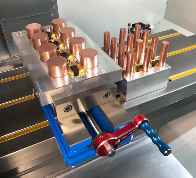
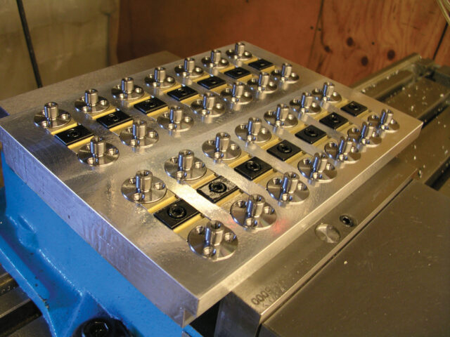
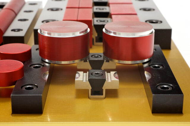
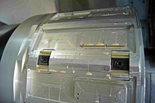
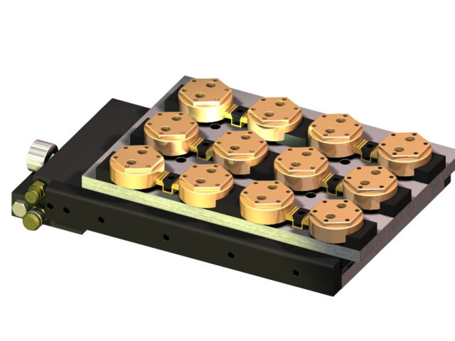
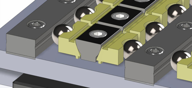
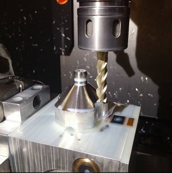
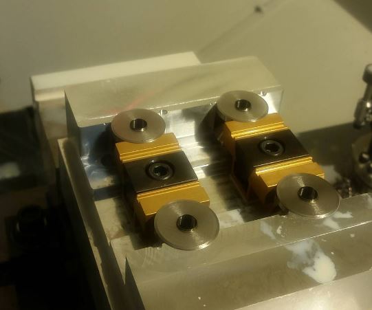
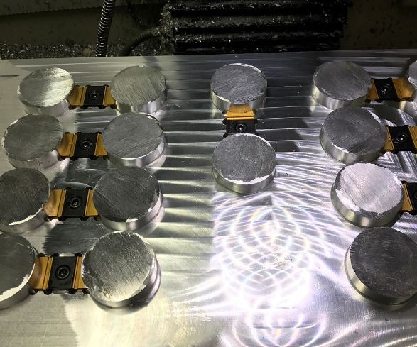
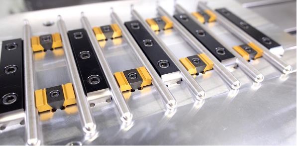
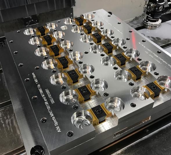
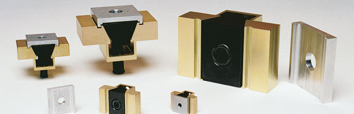
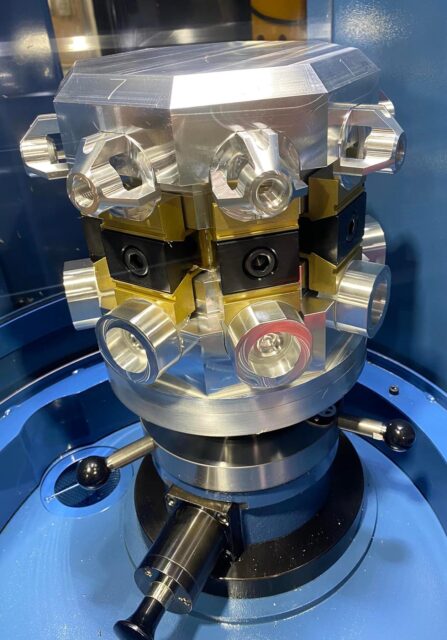
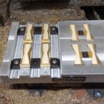
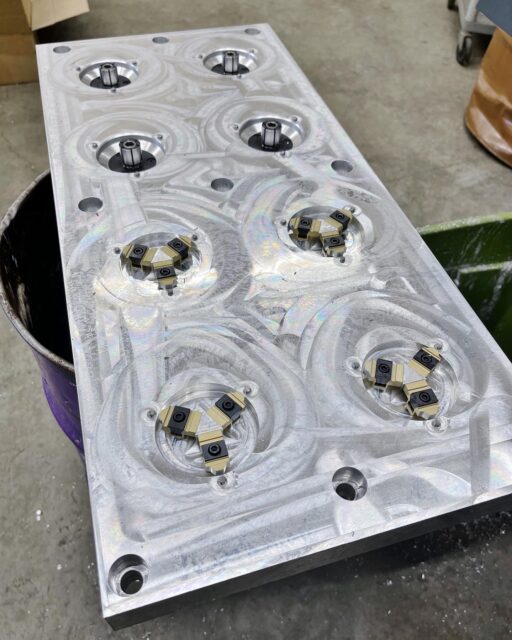
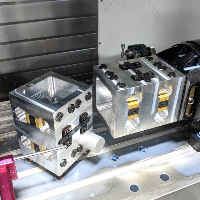
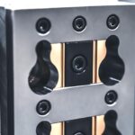
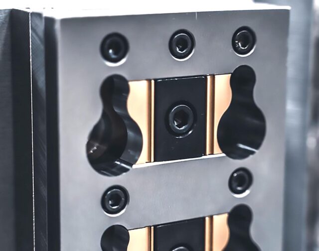
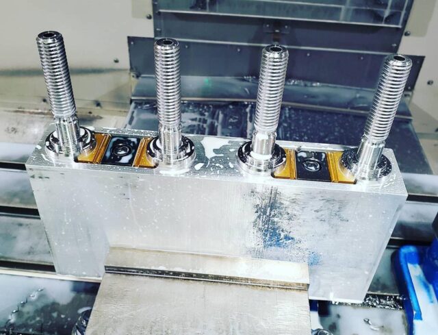
The compact Mitee-Bite Uniforce® clamp is available with extra material on the clamping jaws so it can be machined to conform to the shape of your workpiece – enabling you to fixture unusual applications easily. The specially designed steel wedge spreads the clamping force uniformly on both sides of the 7075-T6 aluminum channel.
A unique locking plate properly expands the clamp while making it rigid for machining the jaws to your specifications, without vibration. Remove locking plate before clamping workpiece. Available in five sizes.
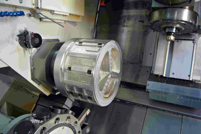
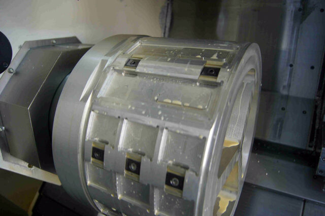
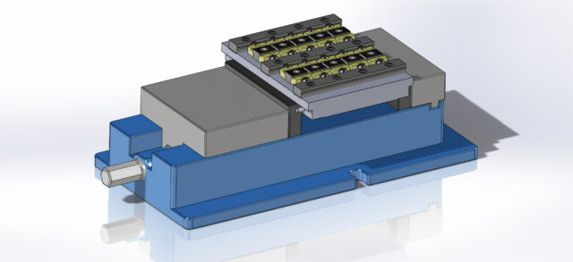
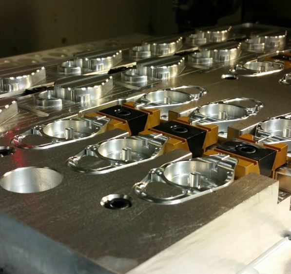
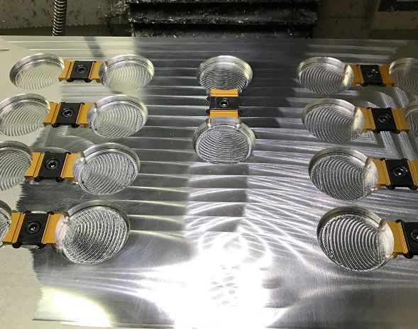
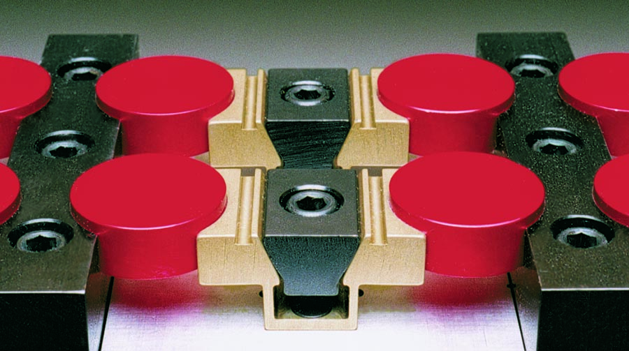
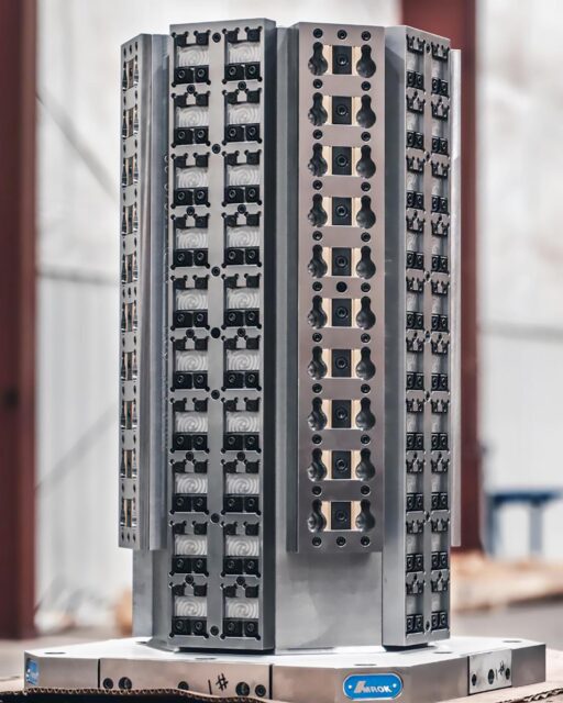
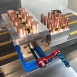
Now you can hold those round and unusual shape parts with ease. This compact workholding will allow more parts per load at a lower price than vise soft jaws. (See Locating Rails)
NOTE: When clamp is used to hold flat stock, use locking plate to machine faces parallel. |
Inch
| Model | Part No. with Locking Plate |
Part No. without Locking Plate |
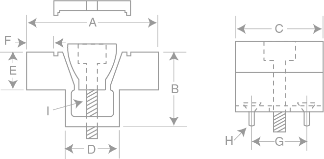
A* | B | C | D | E | F† | G | H** | I | Torque Not To Exceed (Ft/Lbs) |
Holding Force (lbs.) |
Max Torque for Locking Plate (Ft/Lbs) |
Repl. Chan. |
Repl. Steel Wedge |
Repl. Locking Plate |
||
|---|---|---|---|---|---|---|---|---|---|---|---|---|---|---|---|---|---|---|---|
| 500 | 60050 | CAD | 60055 | CAD | 1.125 | .50 | .62 | .420 | .25 | .18 | .400 | 2-56 | 8-32 | 2.5 | 500 | .5 | 60140 | 60310 | 60143 |
| 750 | 60075 | CAD | 60080 | CAD | 1.500 | .75 | .94 | .632 | .37 | .26 | .625 | 6-32 | 1/4-20 | 10.0 | 1,500 | 2 | 60125 | 60320 | 60145 |
| 1000 | 60100 | CAD | 60105 | CAD | 2.000 | 1.00 | 1.25 | .820 | .50 | .39 | .812 | 6-32 | 5/16-18 | 19.0 | 2,500 | 4 | 60135 | 60330 | 60155 |
| 1500 | 60150 | CAD | 60153 | CAD | 3.000 | 1.50 | 1.87 | 1.215 | .75 | .62 | 1.200 | 10-32 | 1/2-13 | 28.3 | 3,500 | 6 | 60160 | 60340 | 60165 |
| 2000 | 60200 | CAD | 60203 | CAD | 4.000 | 2.00 | 2.50 | 1.625 | 1.00 | .80 | 1.625 | 1/4-20 | 5/8-11 | 55.0 | 6,000 | 12 | 60180 | 60350 | 60185 |
F† The amount of machinable stock on jaws.
H** Mounting Screws included.
Metric
| Model | Part No. with Locking Plate |
Part No. without Locking Plate |
A* | B | C | D | E | F† | G | H** | I | Torque Not To Exceed (N.m.) |
Holding Force (N.) |
Max Torque for Locking Plate (N.m.) |
Repl. Chan. |
Repl. Steel Wedge |
Repl. Locking Plate |
||
|---|---|---|---|---|---|---|---|---|---|---|---|---|---|---|---|---|---|---|---|
| 500 | 80050 | CAD | 80055 | CAD | 28.6 | 12.7 | 15.7 | 10.67 | 6.3 | 4.6 | 10.16 | M2 | M4 | 3.40 | 2,225 | .70 | 60140 | 60310 | 60143 |
| 750 | 80075 | CAD | 80080 | CAD | 38.1 | 19.1 | 23.9 | 16.05 | 9.4 | 6.6 | 15.87 | M4 | M6 | 13.50 | 6,675 | 2.7 | 60125 | 60320 | 60145 |
| 1000 | 80100 | CAD | 80105 | CAD | 50.8 | 25.4 | 31.8 | 20.83 | 12.7 | 9.9 | 20.62 | M4 | M8 | 25.00 | 11,125 | 5.0 | 60135 | 60330 | 60155 |
| 1500 | 80150 | CAD | 80155 | CAD | 76.2 | 38.1 | 47.5 | 30.86 | 19.1 | 15.7 | 30.48 | M5 | M12 | 38.40 | 15,575 | 8.0 | 60160 | 60340 | 60165 |
| 2000 | 80200 | CAD | 80205 | CAD | 101.6 | 50.8 | 63.5 | 41.28 | 25.4 | 20.3 | 41.28 | M6 | M16 | 74.60 | 26,700 | 15.0 | 60180 | 60350 | 60185 |
F† The amount of machinable stock on jaws.
H** Mounting Screws included.
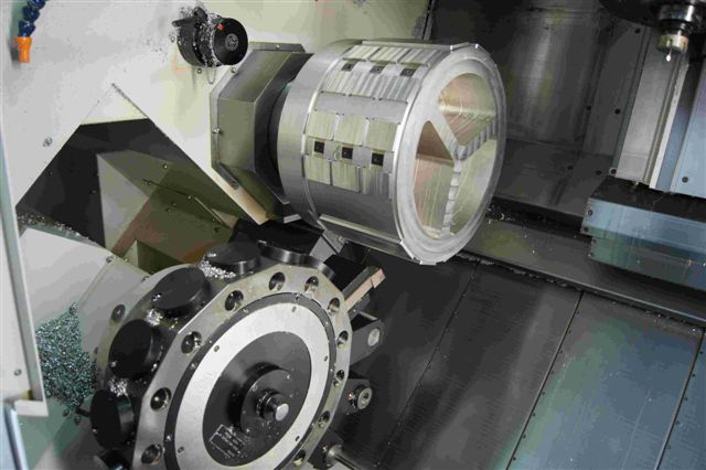
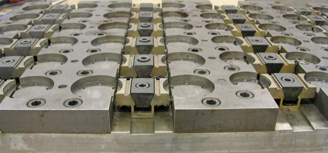
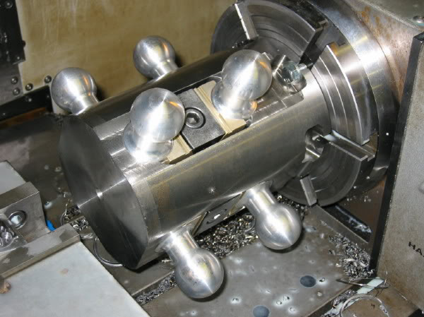
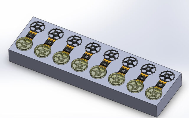
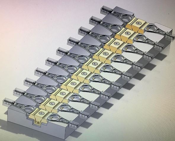
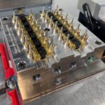
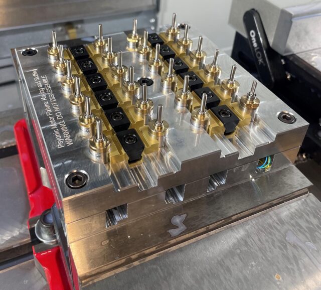
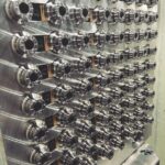
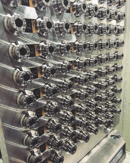
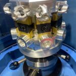
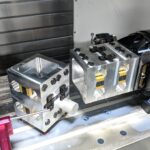
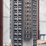
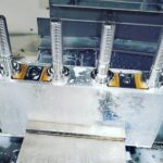
Applications
-
- Image courtesy of Jordan Daugherty
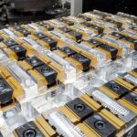
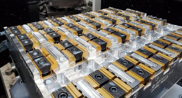
-
- @joem5127 – When lights out production is the goal automation and part density is what matters.
-
- Jonathan Proulz – Mitee-Bite Products Facebook Community
-
- Image courtesy of @rogue_machine

-
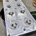
- Images courtesy of @balfanti_machine_works – Pulley Fixture, OP#1 & 2
-
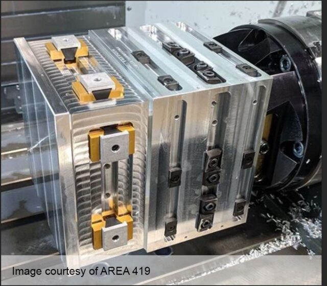
- Image courtesy of @area419official
-
- Image courtesy of @aceroprecision
-
- Image courtesy of Advanced Machine Engineering
-
- Image courtesy of Advanced Machine Engineering
-
- Image courtesy of @ioscnc
-
- Image courtesy of @electrolinkusa