ID Xpansion™ Clamp
Measurements Available: Inch, Metric
ID Xpansion™ Clamps
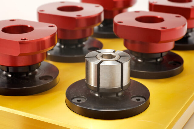
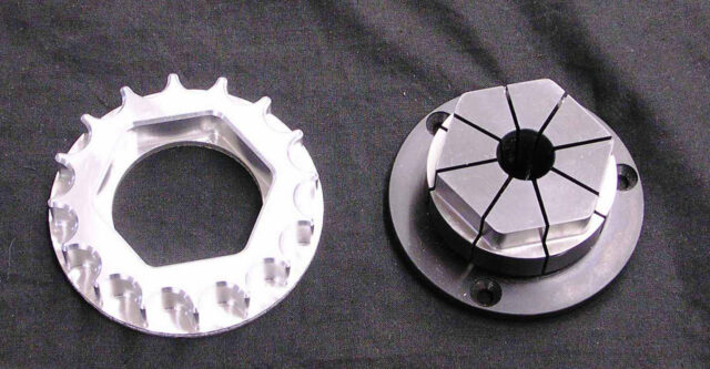
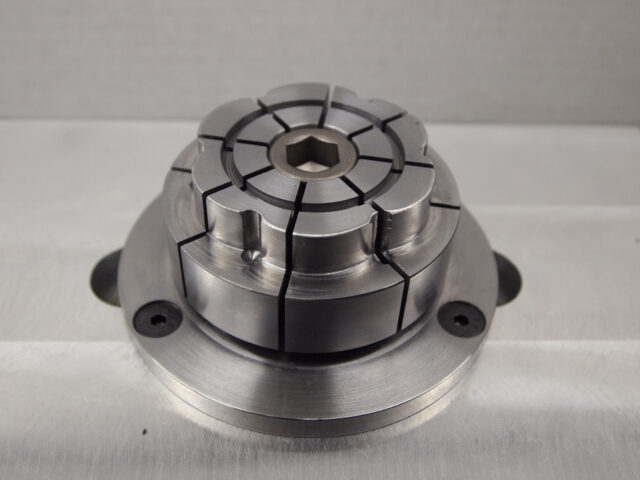
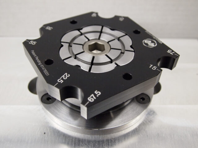
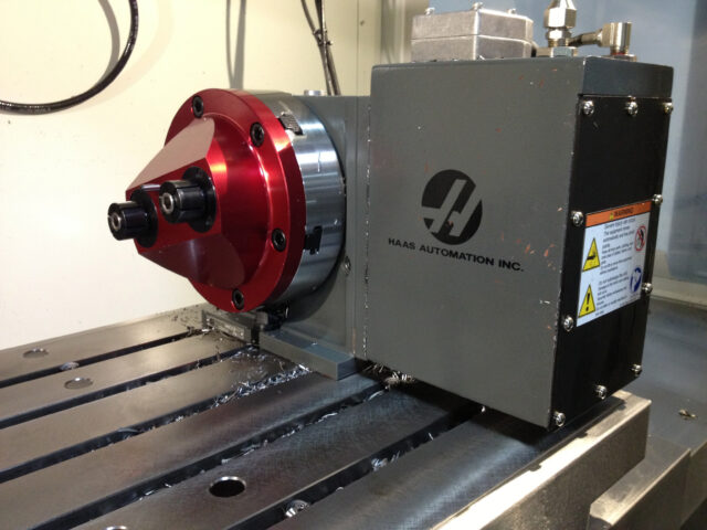
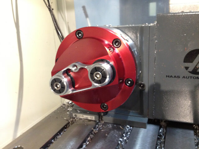
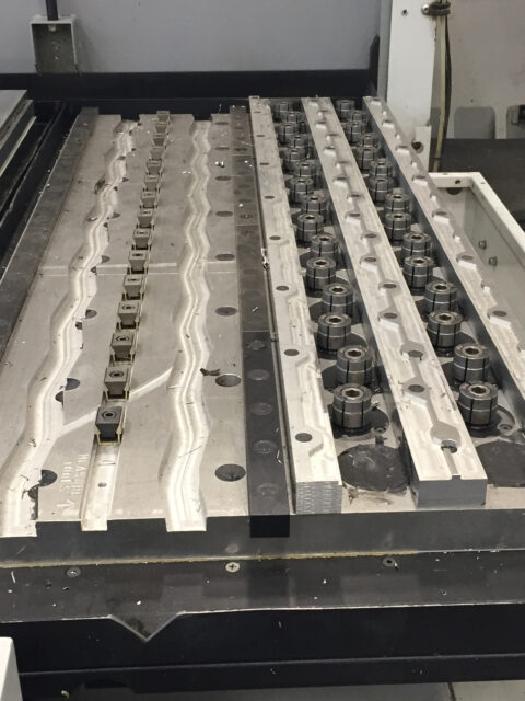
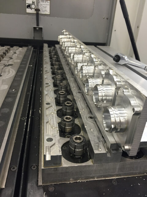
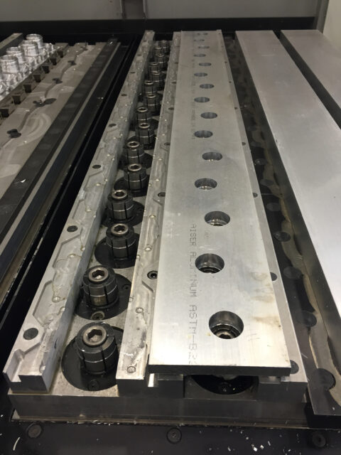
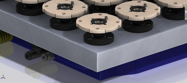
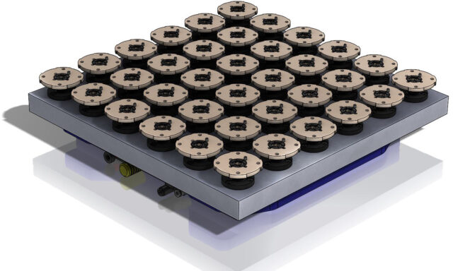
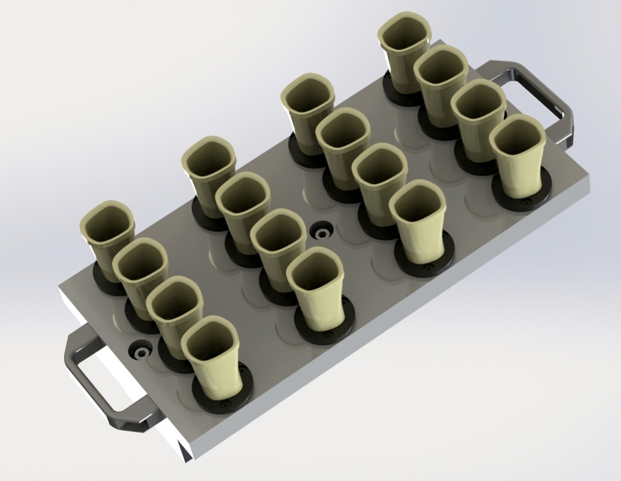
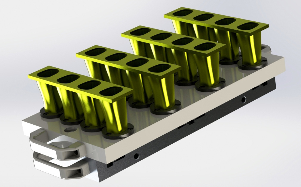
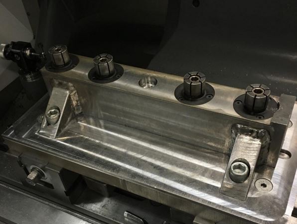
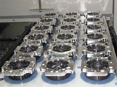
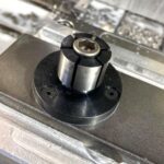
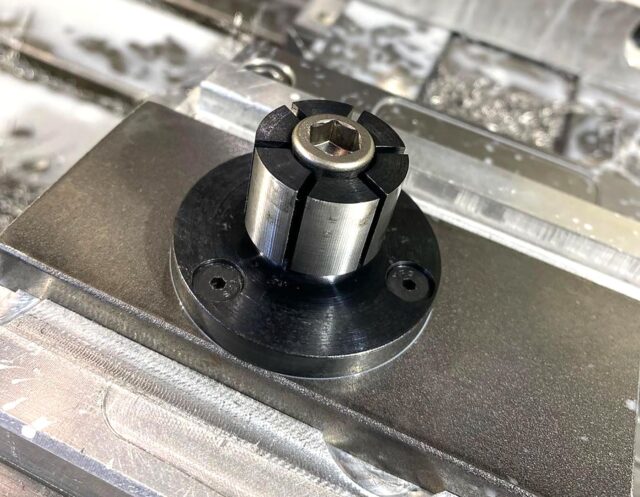
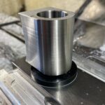
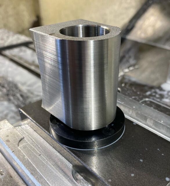
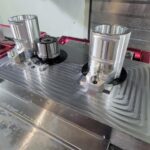
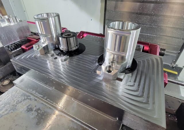
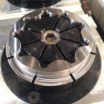
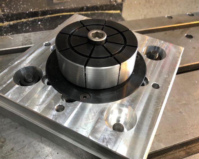
The ID Xpansion™ clamp is the ideal solution to hold parts on an inside diameter for high density machining on vertical or horizontal machining centers. It can also be used as an expanding mandrel on a lathe.
These machinable clamps are produced in 12L14 steel with black oxide coating in 12 sizes and can hold internal diameters from under 3/16 to almost 10 inches (4.1 to 254mm). #10 manufactured using 7075-T6 aluminum.
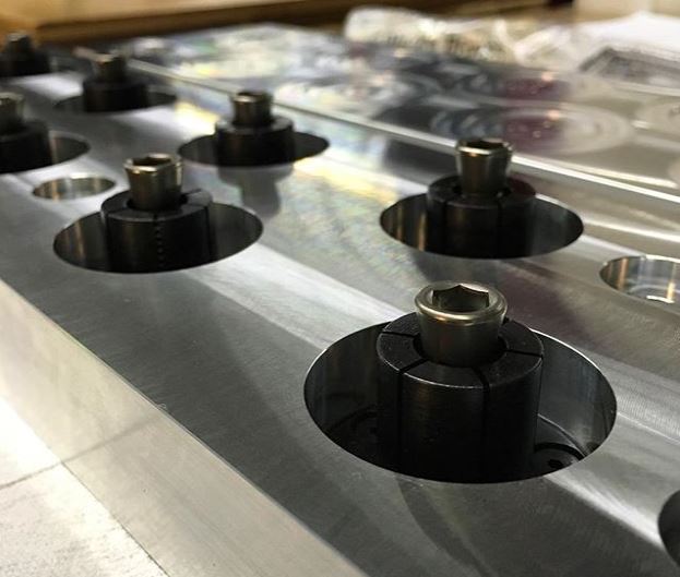
The flange diameter of the clamp is held to a close tolerance for precision locating in a machined pocket on work cubes and fixture plates.
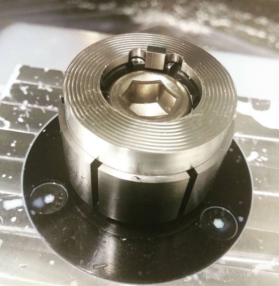
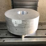
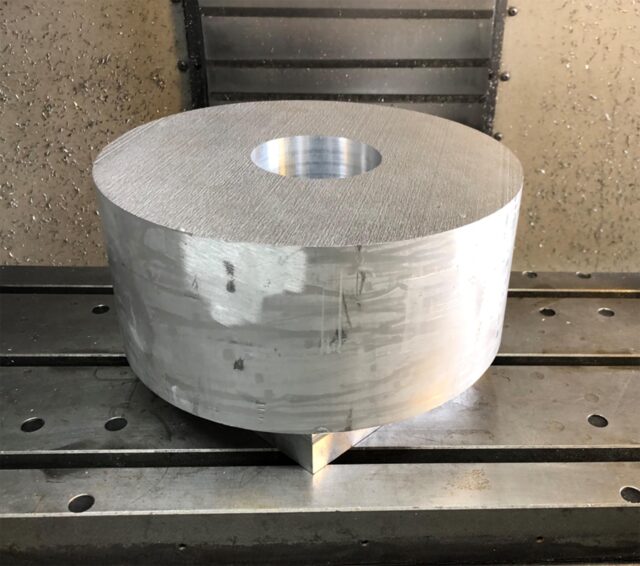
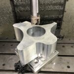
The customer machines the mild steel clamp to match the bore of the part ensuring a proper fit. Often times the clamps can be remachined for different size jobs.
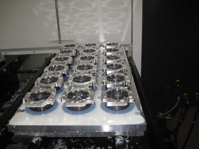
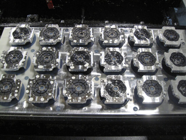
The low profile ID Xpansion™ Clamp can hold several parts in one compact area for secondary operations without any clamping interference. They are quickly tightened with a hex key, torque driver or can be mated to hydraulic pull cylinders for automation.
|
 |
 |
Inch
| Part Number |
Model Number |
A | B | C | D | E+.000 -.002 |
F | G+ | H* | I | J | Torque (Ft/lbs.) |
Holding Force (lbs) |
Replacement Tapered Screws |
|
|---|---|---|---|---|---|---|---|---|---|---|---|---|---|---|---|
| 31000 | #00 | CAD | .42 | .30 | .24 | .12 | .787 | .29 | .16 | 2-56 on .540 BHC | 2-56 x 1/2 | .16 | 0.5 | 250 | 31001 |
| 31050 | #0 | CAD | .86 | .63 | .59 | .23 | 1.170 | .49 | .28 | 6-32 on .825 BHC | 8-32 x 1 | .30 | 3.6 | 950 | 31002 |
| 31100 | #1 | CAD | .98 | .75 | .59 | .23 | 1.240 | .56 | .48 | 6-32 on .910 BHC | 1/4-20 x 1 1/4 | .50 | 13.3 | 1,900 | 31010 |
| 31150 | #2 | CAD | .98 | .75 | .59 | .23 | 1.476 | .79 | .53 | 6-32 on 1.140 BHC | 5/16-18 x 1 1/4 | .56 | 27.6 | 2,500 | 31020 |
| 31200 | #3 | CAD | 1.13 | .88 | .69 | .25 | 1.968 | 1.06 | .71 | 8-32 on 1.550 BHC | 3/8-16 x 1 1/2 | .71 | 49.3 | 4,500 | 31032 |
| 31250 | #4 | CAD | 1.25 | 1.0 | .81 | .25 | 2.205 | 1.39 | .90 | 8-32 on 1.790 BHC | 1/2-13 x 1 1/2 | .71 | 120.0 | 5,900 | 31042 |
| 31300 | #5 | CAD | 1.56 | 1.25 | 1.06 | .31 | 2.736 | 1.65 | 1.15 | 10-32 on 2.200 BHC | 5/8-11 x 1 3/4 | .79 | 224.0 | 10,000 | 31052 |
| 31350 | #6 | CAD | 1.56 | 1.25 | 1.06 | .31 | 2.972 | 2.03 | 1.15 | 10-32 on 2.515 BHC | 5/8-11 x 1 3/4 | .79 | 224.0 | 10,000 | 31052 |
| 31400 | #7 | CAD | 1.79 | 1.48 | 1.27 | .31 | 4.232 | 3.06 | 1.15 | 1/4-20 on 3.646 BHC | 5/8-11 x 2 | .79 | 224.0 | 10,000 | 31072 |
| 31450 | #8 | CAD | 1.79 | 1.48 | 1.27 | .31 | 5.232 | 4.06 | 1.15 | 1/4-20 on 4.648 BHC | 5/8-11 x 2 | .79 | 224.0 | 10,000 | 31072 |
| 31500 | #9 | CAD | 1.79 | 1.48 | 1.27 | .31 | 5.232 | 6.89 | 1.15 | 1/4-20 on 4.648 BHC | 5/8-11 x 2 | .79 | 224.0 | 10,000 | 31072 |
| 31550** | #10 | CAD | 1.79 | 1.48 | 1.27 | .31 | 6.000 | 9.85 | 1.15 | 1/4-20 on 5.250 BHC | 5/8-11 x 2 | .79 | 125.0 | 6,000 | 31072 |
Metric
| Part Number |
Model Number |
A | B | C | D | E+.000 -.050 |
F | G+ | H* | I | J | Torque (N.m.) |
Holding Force (N.) |
Replacement Tapered Screws |
|
|---|---|---|---|---|---|---|---|---|---|---|---|---|---|---|---|
| 38000 | #00 | CAD | 10.7 | 7.6 | 6.1 | 3.0 | 20.0 | 7.4 | 4.1 | M2 on 13.7 BHC | M2x12 | 4.1 | .70 | 1,113 | 38001 |
| 38050 | #0 | CAD | 21.8 | 16.0 | 15.0 | 5.9 | 29.72 | 12.4 | 7.1 | M3 on 20.95 BHC | M4x25 | 7.2 | 5.00 | 4,228 | 38002 |
| 38100 | #1 | CAD | 24.9 | 19.0 | 15.0 | 5.9 | 31.5 | 14.2 | 12.2 | M3 on 23.1 BHC | M6x30 | 11.2 | 17.00 | 8,455 | 38010 |
| 38150 | #2 | CAD | 24.9 | 19.0 | 15.0 | 5.9 | 37.5 | 20.0 | 13.5 | M3 on 29.0 BHC | M8x30 | 13.2 | 34.00 | 11,125 | 38020 |
| 38200 | #3 | CAD | 28.6 | 22.2 | 17.5 | 6.4 | 50.0 | 27.0 | 18.0 | M4 on 39.4 BHC | M10x35 | 16.3 | 60.00 | 20,025 | 38032 |
| 38250 | #4 | CAD | 31.8 | 25.4 | 20.6 | 6.4 | 56.0 | 35.3 | 23.0 | M4 on 45.5 BHC | M12x40 | 20.3 | 150.00 | 26,255 | 38042 |
| 38300 | #5 | CAD | 39.6 | 31.8 | 27.0 | 7.9 | 69.5 | 42.0 | 29.3 | M5 on 55.9 BHC | M16x45 | 21.4 | 280.00 | 44,500 | 38052 |
| 38350 | #6 | CAD | 39.6 | 31.8 | 27.0 | 7.9 | 75.5 | 51.5 | 29.3 | M5 on 63.9 BHC | M16x45 | 21.4 | 280.00 | 44,500 | 38052 |
| 38400 | #7 | CAD | 45.5 | 37.6 | 32.3 | 7.9 | 107.5 | 77.7 | 29.3 | M6 on 92.6 BHC | M16x50 | 19.3 | 280.00 | 44,500 | 38072 |
| 38450 | #8 | CAD | 45.5 | 37.6 | 32.3 | 7.9 | 132.9 | 103.0 | 29.3 | M6 on 118.06 BHC | M16x50 | 19.3 | 280.00 | 44,500 | 38072 |
| 38500 | #9 | CAD | 45.5 | 37.6 | 32.3 | 7.9 | 132.9 | 175.0 | 29.3 | M6 on 118.06 BHC | M16x50 | 19.3 | 280.00 | 44,500 | 38072 |
| 38550** | #10 | CAD | 45.5 | 37.6 | 32.3 | 7.9 | 152.4 | 250.2 | 29.3 | M6 on 133.35 BHC | M16x50 | 19.3 | 170.00 | 26,000 | 38072 |
H* – (3) Mounting Screws Included. (4) Mounting Screws Included with #9 & #10.
** – Clamp made from 7075-T6 aluminum stock.
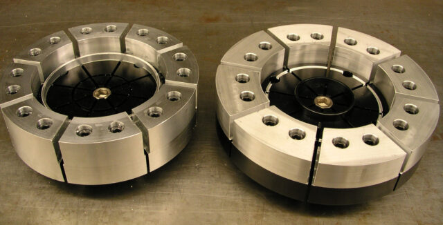
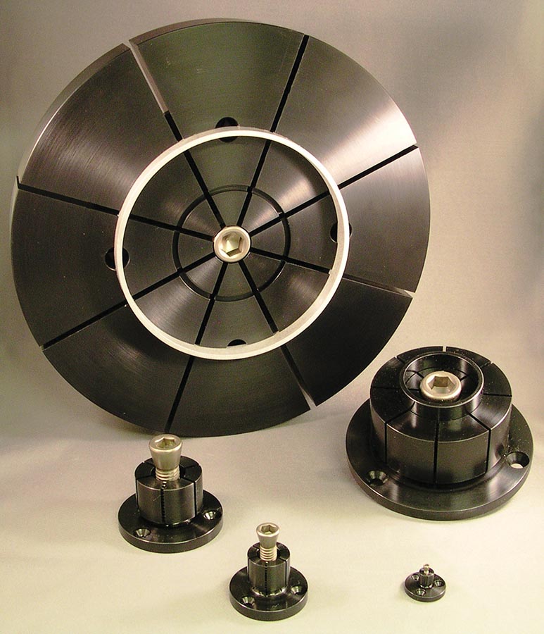
| MODEL #00 – #6 ID Xpansion™ Clamps |
|
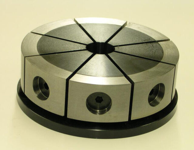
| MODEL #7-10 ID Xpansion™ Clamps |
GENERAL NOTES: ID Clamps #00 through #9 are manufactured from 12L14 “Free Machining” low carbon steel. The #10 ID Clamp is manufactured from 7075-T6511 “High Strength” aluminum alloy. Aggressive material removal rates/practices are not recommended when machining ID Clamps “to size”. For blind hole applications, please see our Manual Actuators, or contact us for the availability of custom screws and other mounting/use options. |
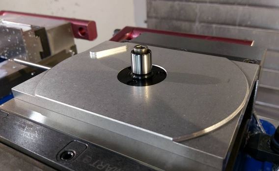
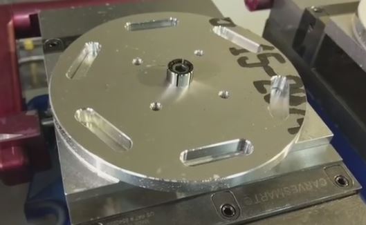
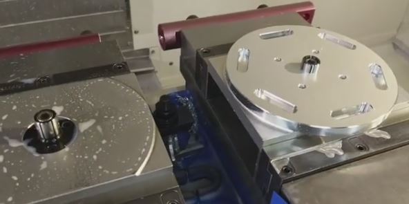
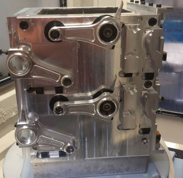
Applications
-
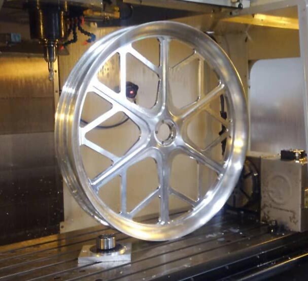
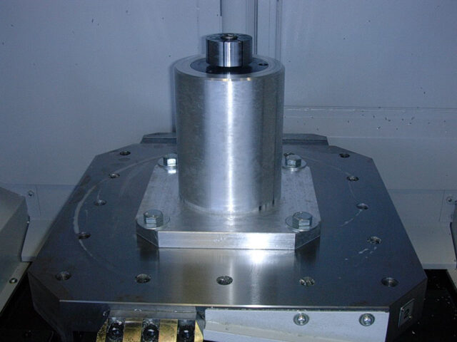
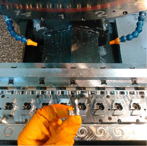
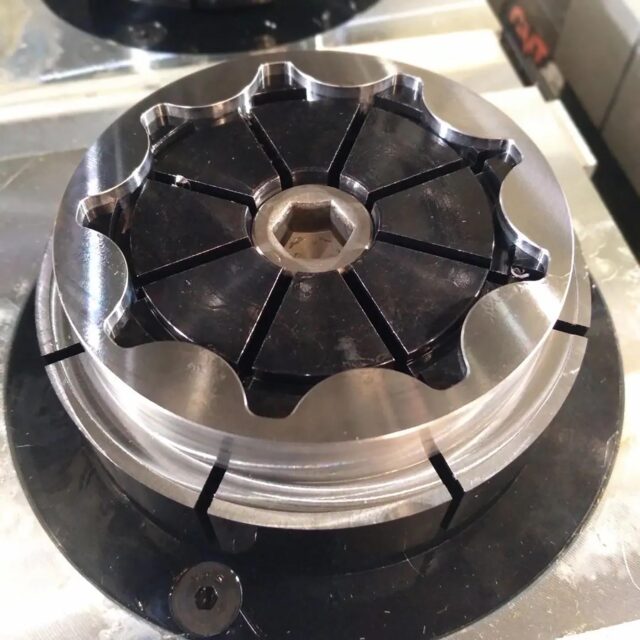
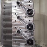
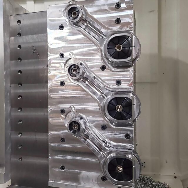
- @sutcliffe_mechanical – Trying out some ID clamps today. I was kinda scared. Not sure if the part was gonna move or not. Everything worked out great. Cant wait to use more of these in the future.
-
- @sutcliffe_mechanical – Trying out some ID clamps today. I was kinda scared. Not sure if the part was gonna move or not. Everything worked out great. Cant wait to use more of these in the future.
-
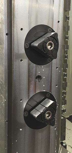
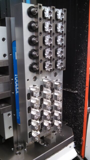
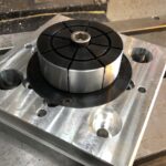
- Jonathan Rubio – MiteeBite Products Facebook Community – Thanks for the group add. This place is cool for inspiration. Heres an ID clamp fixture I’ve used in the past.
-
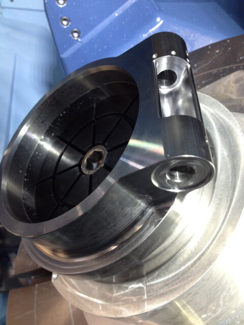
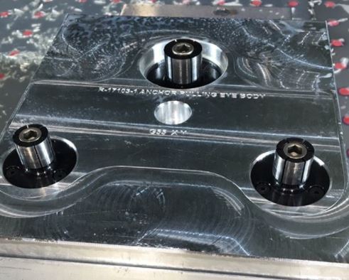
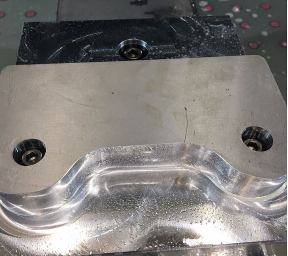
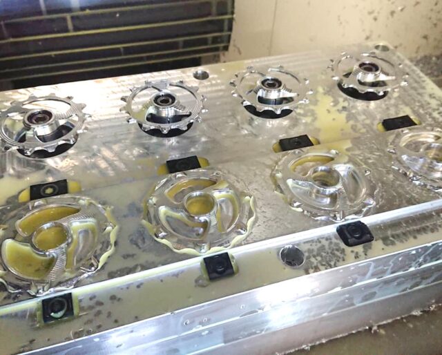
- Image courtesy of @jose.of.all.trades24. “These @miteebite ID Xpansion clamps really came thru today! Amazing!”
-
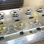
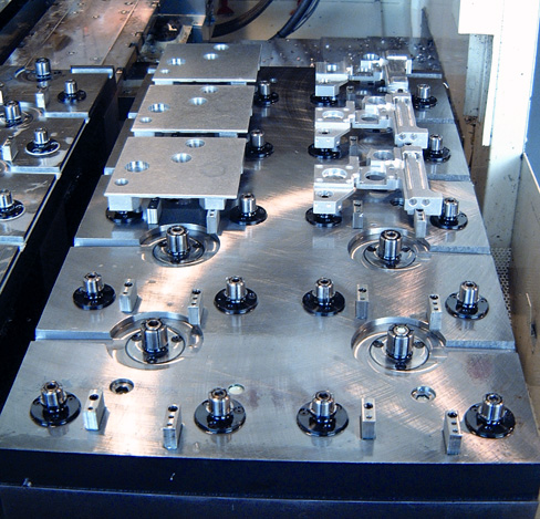
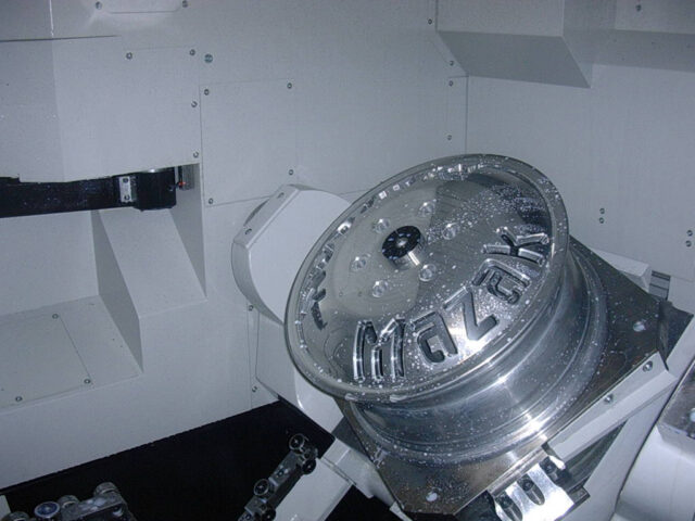
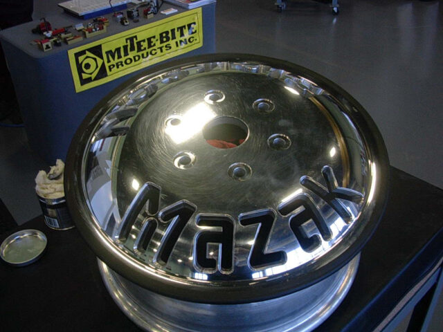
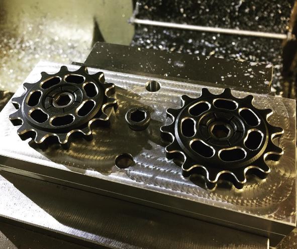
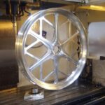
- Image courtesy of @cape_town_cnc
-
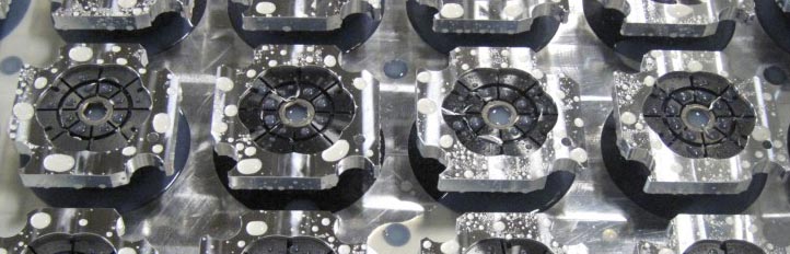
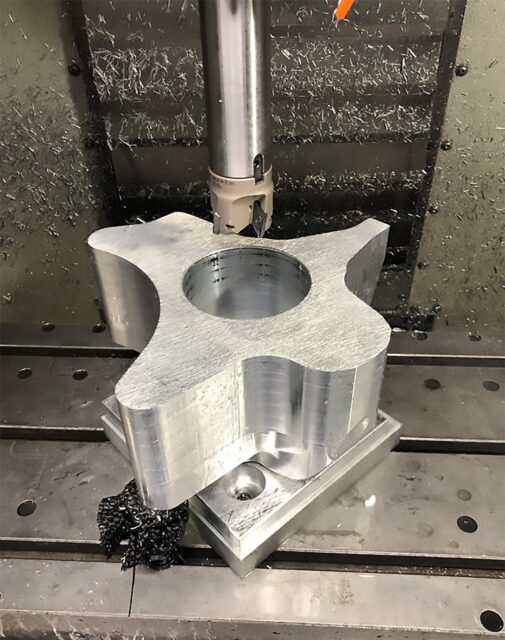
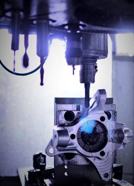
- Photo credit @erik_hardy
-
- Photo credit @erik_hardy
-
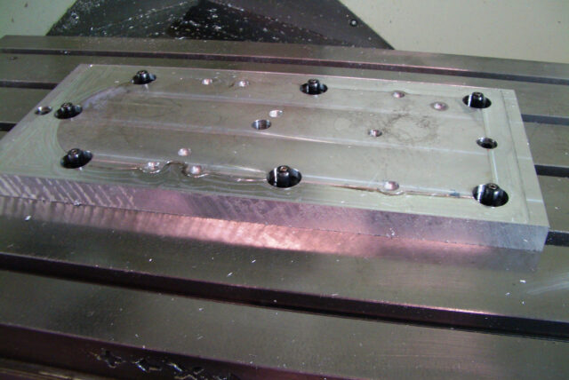
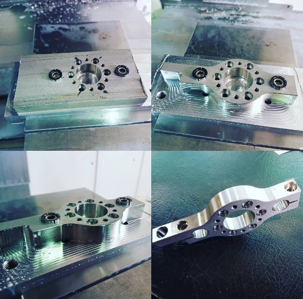
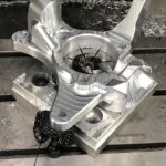
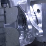
- 3 – OP3- Photo credit @erik_hardy
-
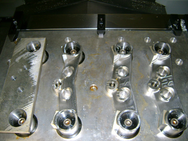
- 4 – OP3B – Photo credit @erik_hardy
-
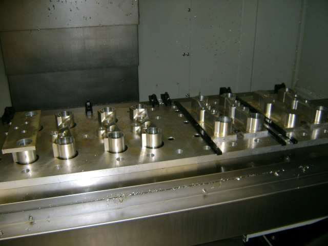
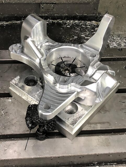
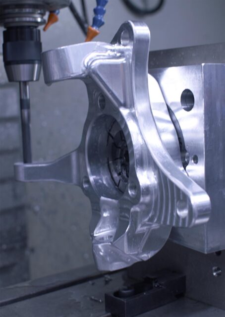
- 5 – OP5 – Photo credit @erik_hardy
-
- 6 – final – Photo credit @erik_hardy
-

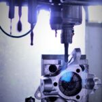
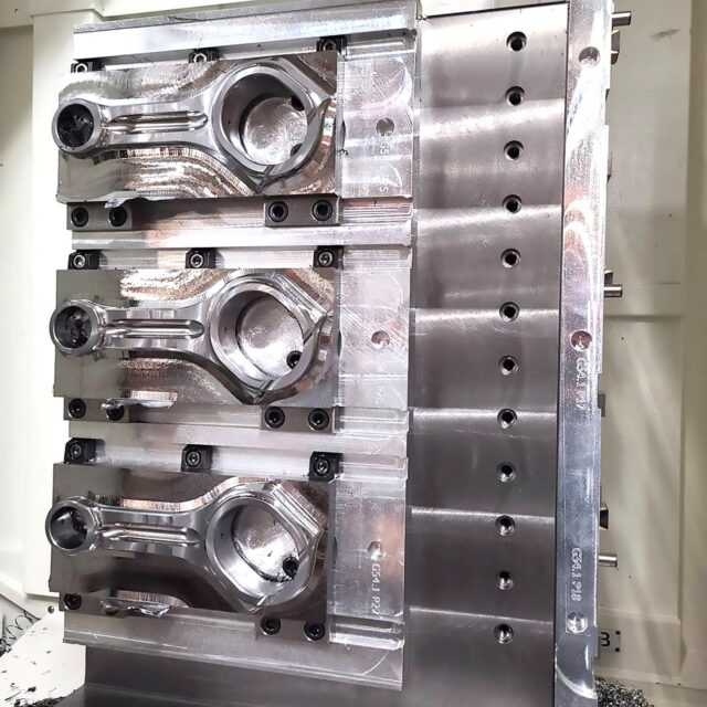
- OP1 – Photo credit @jprecisionmachine
-
- Photo credit @djprecisionmachine
-
- Image courtesy of revolutionscnc